-
San Marino Commissioning of Single-Fiber Bidirectional PAM4
Experimental and simulation data of 400 Gb/s plus per lane with PAM4, 6, 8 optical transmission and scheme of C2C/C2M with optical PHY. Most of this contribution has been presented in “oif2025. Why bring optics closer to the SoC? The first 16-wavelength bidirectional link. Microrings with inductorless driver and analog front end enable 0. 6 It is a multiplexer! THREE RECORD-SETTING GENERATIONS OF PHOTONIC HARDWARE IN VALIDATION. This guide explains how bidirectional communication works in the 100G Ethernet standard to effectively double the density of your existing fiber strands. Bidirectional fiber delivers multiple practical benefits to 100G. BiDi transceiver, a compact optical transceiver with WDM (wavelength division multiplexing) technology and SFP multi-source protocol (MSA) compliance, allows fast data transmission using a single fiber optic for both sending and receiving signals, saving resources and cutting infrastructure costs. The next generation dual-rate BiDi, which has both 40Gb and 100Gb operational modes.
[PDF Version]
-
Relay Protection Commissioning Specialist
1,148 Relay Protection Commissioning jobs available on Indeed. Apply to Commissioning Engineer, Commissioning Manager, Designer and more!Job Summary: Seeking a highly skilled and experienced Commissioning Manager to oversee the commissioning and startup activities of energy storage projects. This role will ensure that all projects are commissioned in accordance with company standards, regulatory requirements, and industry best. The testing and verification of relay protection devices can be divided into four groups: Type tests are needed to prove that a protection relay meets the claimed specification and follows all relevant standards. Since the basic function of a protection relay is to correctly function under abnormal. Senior Relay Settings Engineer - Salt Lake City, UT. Electrical commissioning is the process of validating that newly installed or modified equipment performs to OEM specifications and integrates seamlessly with protection and control schemes. This is distinct from maintenance testing, which verifies performance over time. Electrical panels (up to 480V 3-phase).
[PDF Version]
-
System Station Relay Protection Commissioning
This paper suggests a process for performing consistent and thorough commissioning tests through many sources: breaking out relay logic into schematic drawings; using SER, metering, and event reports from relays; simulating performance using end-to-end testing and lab. This paper suggests a process for performing consistent and thorough commissioning tests through many sources: breaking out relay logic into schematic drawings; using SER, metering, and event reports from relays; simulating performance using end-to-end testing and lab. Abstract—Performing tests on individual relays is a common practice for relay engineers and technicians. Most utilities have a wide variety of test plans and practices. However, properly com-missioning an entire protection system, not just the individual relays, presents a challenge. Relay systems protect high-voltage equipment and transmission lines to ensure safe, stable systems. This is distinct from maintenance testing, which verifies performance over time. 0) - 2948492 and the Ergon Energy Protection.
[PDF Version]
-
How much does fiber optic splicing and testing cost
Typical rates range from $75 to $180 per hour per technician, with on-site time often dominating the total. Hidden costs include traffic control, trench restoration, and post-repair verification testing. The "per splice" rate is the most. Users typically pay for fiber optic repair based on problem location, accessibility, and required restoration. Includes fusion/splice, testing, and basic materials. I usually bill T&M, but it works out to about $175-250 for setup/teardown per site and $4-7 per fiber for prep in a new tray in an existing case and splicing depending on if it's flooded or dry cable. Understanding these factors can help businesses and individuals budget effectively for fiber optic.
[PDF Version]
-
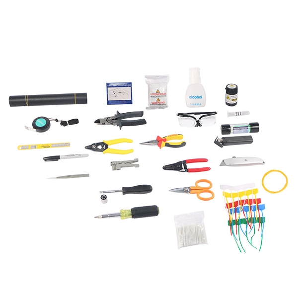
How to connect the white protective tube for fiber optic cable splicing
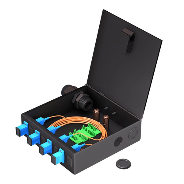
By following these detailed steps, the installation of your Fiber Splice Closure will be secure, organized, and maintained, ensuring high performance and longevity of your fiber optic network. Installing a fiber optic splice closure efficiently and effectively requires attention to detail and. Learn how to splice fiber optic cable step by step in this complete guide! In this video, you'll see the full fiber splicing process — from fiber preparation, cleaving, and fusion splicing to final testing. Whether you're a. The operation and skills of fiber optic fusion splicing technology can be mainly divided into five steps: fiber stripping, fiber cutting, fiber melting, fiber sleeve, and fiber winding. What is Fiber Optic Splicing and Why is it Needed? – #1. Splices are generally placed in a splice tray which is then placed inside a splice closure or integrated into a fiber pedestal for OSP.
[PDF Version]
-
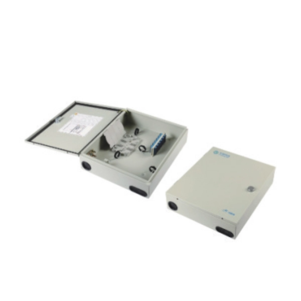
Should there be a protective cover for the secondary distribution box
All pull boxes, junction boxes, and fittings shall be provided with covers identified for the purpose. If metal covers are used, they shall be grounded. Where cable is used, each cable shall be secured to the. This document describes the minimum requirements for the design and installation of electric conduits and pulling insulated cables. These covers come in various shapes and sizes, tailored for different applications and environments. However, electrical panels are only one of the most.
[PDF Version]
-
What is the protective grounding of a distribution box
26 mm 2 (10 AWG) ground wire must be used, and in all other markets a 6 mm 2 must be used. On the US market, a 5. Each DISTRIBUTION BOX and controller must be grounded. Grounding of the units: Attach a ground wire from one of. Whether you're a seasoned pro or just starting out, this comprehensive guide will give you practical insights into proper grounding techniques, with a special focus on how selecting quality materials from a reliable building material supplier impacts your entire system's safety and longevity. Grounding is a mechanism to protect distribution equipment and people under normal operating conditions, abnormal operational (overcurrent and overvoltage) responses, and hazardous conditions such as shocks. This helps to reduce the potential difference that exists between conductive parts and the earth. Protective grounds must be installed so all phases of lines or cable are visibly and effectively bonded together in a multi-phase. Proper grounding is the non-negotiable foundation of electrical safety.
[PDF Version]
-
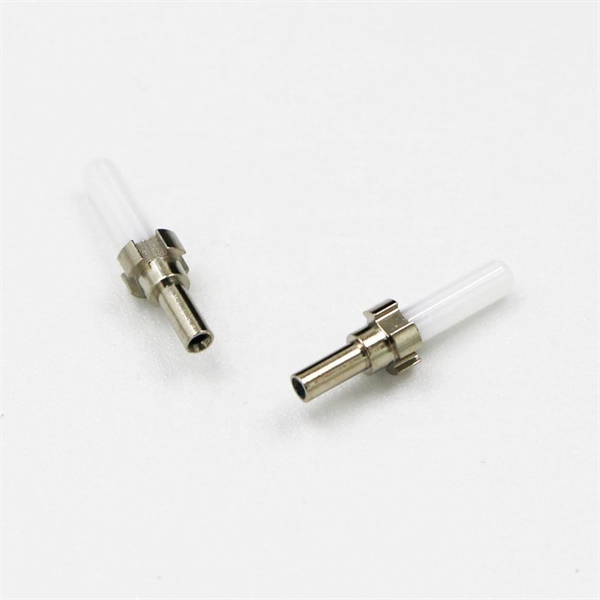
What specifications should be used for optical cable protective sleeves
The FP-03 series is the industry standard for durable and lasting protection of single fiber splices in field installations, while the FP-04 (T)/05 provide these same performance levels for 8/12 fiber ribbon respectively. FinishAdapt's fusion splice protector sleeves are designed to restore the environmental and mechanical integrity of optical fiber cables after fusion splicing. After two fibers are precisely fused using a fusion splicer, the splice is fragile and needs protection from physical. AFL offers a wide selection of fiber protection sleeves to meet any application. The strength member within the sleeve is made of. iFiber Optix Fiber Optic Splice Sleeves protect and reinforce fusion-spliced fiber connections — restoring the mechanical strength of the spliced fiber and shielding the splice point from environmental stress, physical disturbance, and long-term degradation.
[PDF Version]
-
Thickness of galvanized pipe cable tray protective sleeve
239-inch minimum thickness; round tube closed with welded longitudinal joint, with tabs for s e, tapered-cup shaped, and smooth space between sleeve and raceway or cable. Provide sealing elementsus-trations without notice. All illustrations, descriptions and technical information included in this document are provided as indications and can cable trays are equivalent. The mechanical and electrical characteristics, tests, certifications, overall quality management, recommendations mentioned. Cable Trays are designed to meet most requirements of cable and electrical wire installations and comply to local and international standards of fabrications and finishes. Include type and number required for. Cast-Iron Wall Pipes: Cast or fabricated of cast or ductile iron and equivalent to ductile-iron pressure pipe, with plain ends and integral waterstop unless otherwise indicated.
[PDF Version]
-
Protective plate for the support of the three-level distribution box
A support plate serves as the foundational skeleton within a waterproof distribution box, ensuring that heavy switchgear and sensitive wiring remain secure despite external vibrations or mounting challenges. A high-quality support plate facilitates the organized mounting of DIN rails and terminal. Different mounting plates for multiple uses in electrical cabinets Delvalle. Galvanized: it is the most common. Three cULus listed models made of 16-guage galvanized steel are available to meet a variety of applications. Two diferent 12”x12”. This construction site distribution box is constructed from cold-rolled steel plates, providing a dependable temporary power solution ideal for steelwork, woodworking machinery, and more. Its rainproof design features a sloping roof and reinforced triangular brackets for enhanced stability and. In this guide, we'll break down everything you need to know to install a distribution box correctly and confidently. Choose the right box based on environment (indoor/outdoor), load capacity, and durability. Check for proper IP/NEMA ratings and material quality.
[PDF Version]
-
Testing of Optical Digital Relay Protection
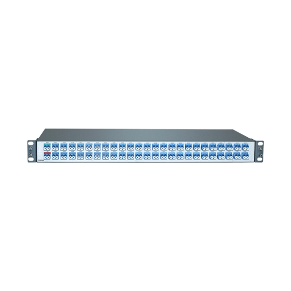
Our relay protection tester offers comprehensive testing for both optical digital and traditional protective devices. It's ideal for power plants, substations, equipment manufacturers, and institutions needing relay protection evaluations. They are like the “eyes” and “nerves” of the system, constantly monitoring the health status of the power grid and quickly responding to faults to ensure the safety of personnel and equipment. To ensure the. This product integrates an optical digital network signal analyzer and an optical digital relay protection tester. Comprehensive and practical testing functions, supporting AC tests, group tests, status sequences, phase verification, polarity, virtual terminals, differential protection, distance. IEC Standard 61850 Optical Digital Relay Protection Test System GDJB-61850 Product Description developed this new portable product.
[PDF Version]
-
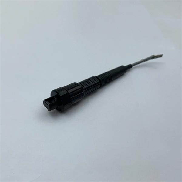
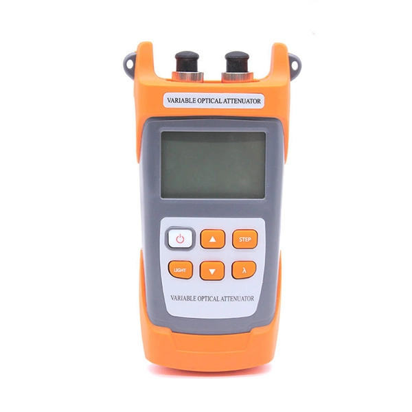
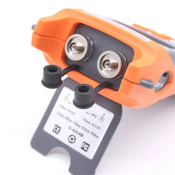
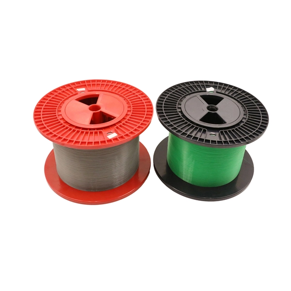
What are the methods for testing the reliability of pigtail fibers
There are several common methods used to assess various aspects of fiber optic performance, including continuity testing, insertion loss testing, return loss testing, and Optical Time Domain Reflectometer (OTDR) testing. Testing the integrity and performance of fiber optic cables is essential for maintaining the reliability and efficiency of telecommunications networks. Key tests include: Effective fiber testing utilizes advanced tools such as Optical. The primary purpose of fiber integrity testing — required by Telcordia GR-468-CORE, Issue 2 for all optoelectronics and integrated modules with fiber pigtails — is to ensure the attachment of a fiber pigtail to a package. The three main methods for fiber optic.
[PDF Version]
-
Find Chip and Packaging Testing of Optical Modules
Most significantly, leading providers of AI and HPC devices like NVIDIA and Intel are pursuing a variety of probing methods, fiber alignment strategies, and connector approaches to determine the best methods for testing at the wafer, package, and system levels. By moving optical transceivers from the fronts of racks into the same package as the networking switch and HBMs, AI programs that used to. This paper discusses the evolution of both conventional and advanced packaging technologies and outlines future directions for design, fabrication, and packaging using glass substrates and femtosecond laser processing. Introduction The challenges in modern HPC, AI, and data communication systems. Information and communication technology (ICT) is projected to drive 20% of global electricity consumption by 2030, with data centers at the heart of the demand. It's critical. At the same time, to achieve larger capacity and higher integration, development of optical interfaces using Co-Packaged Optics (CPO) technology, which are fundamentally different form to current optical transceiver interfaces, is in progress. The CPO is a package in which an optical module and a.
[PDF Version]
-
Temperature Sensing Optical Cable Testing
High-definition temperature sensing based on the natural Rayleigh backscatter in optical fiber delivers a virtually continuous line of temperature measurements with sub-millimeter spatial resolution. 1. Map temperat.
[PDF Version]
-
Indoor Optical Cable Flame Retardant Testing Standards
The International Electrotechnical Commission answers the first question with IEC 60332, “Tests on electric and optical-fibre cables under fire conditions – Part Tests for vertical flame propagation. ”Corning Optical Communications manufactures quality flame retardant optical fiber cables for indoor applications, which comply with the requirements of the National Electric Code® (NEC® 2023) published by the National Fire Protection Agency (NFPA). It eliminates the need f OM4) starting from 2 all the way to 48 fibers. Our cables are stocked res to ensure communication systems integri e charged with enforcing the Life Safety Code. In many states the AHJ are the state fire marshals ho have local. This short guide explains the commonly used materials — LSZH and PVC — how industry fire-rating systems (plenum, riser, vertical flame tests) work, and practical tradeoffs so you can pick the right cable for the space and code requirements.
[PDF Version]
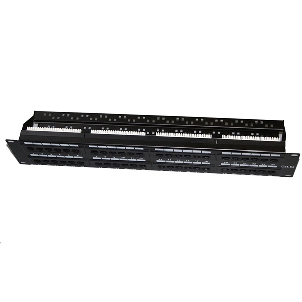
Telecom Racks & Cabinets
19-inch racks, wall-mount cabinets, open frames with high load capacity and seismic rating.
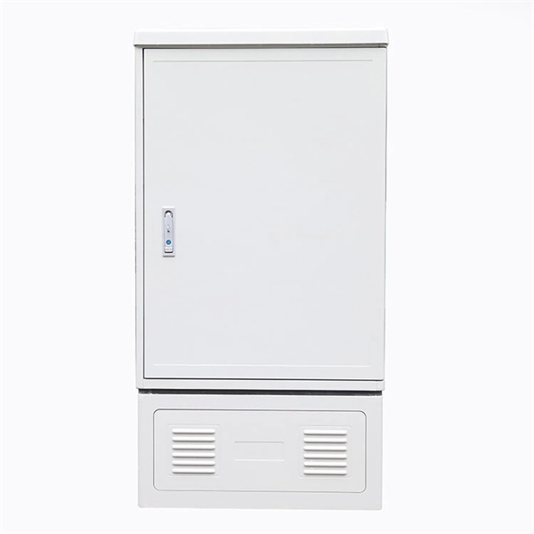
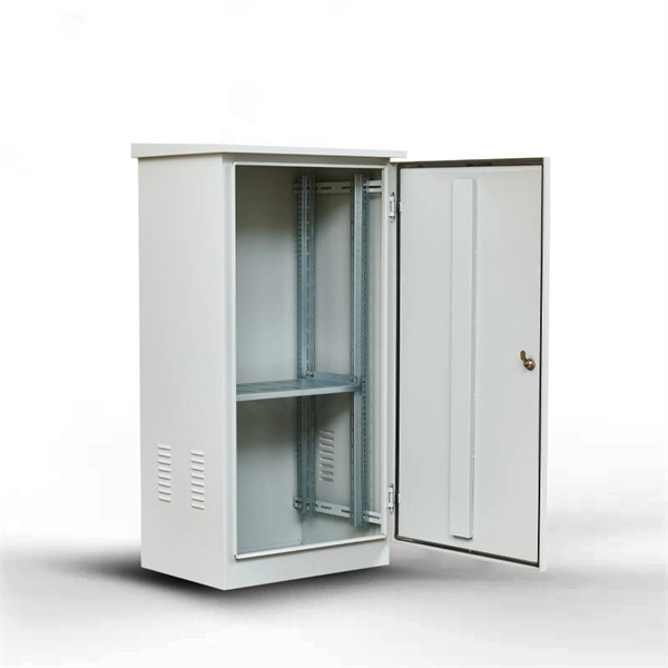
Outdoor Climate Cabinets
IP55/IP66 outdoor enclosures with integrated cooling/heating, -40°C to +55°C operation.
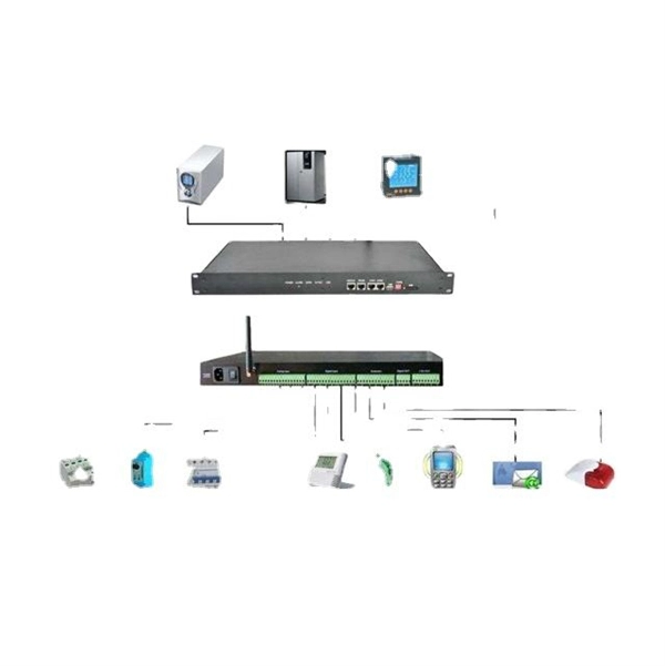
Smart PDUs & Power Distribution
Intelligent PDUs with remote monitoring, per-outlet switching, and environmental sensors.
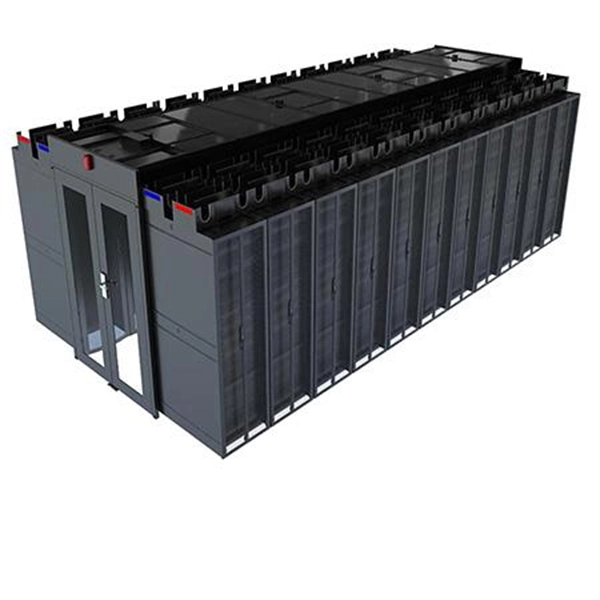
Shelters & Network Cabinets
Prefabricated telecom shelters, emergency comms shelters, and network cabinets with cable management.