-
Online Verification of Relay Protection Setting Values
Calculate pickup values, timing curves, coordination time intervals (CTI), and test injection currents for overcurrent (50/51), differential (87), distance (21), and directional (67) protective relays. Essential tool for relay technicians, protection engineers, and. Relay protection is a crucial aspect of electrical power network transmission and distribution systems. According to the method, the regional power grid is divided into multiple subareas according to the practical situation of operation of the regional power grid; a power grid. The North American Electric Reliability Corporation (NERC), under the direction of the Federal Energy Regulatory Commission (FERC), is responsible for improving the reliability of the North American bulk electric system (BES). This responsibility includes creating a compliance program to improve.
[PDF Version]
-
Case Study of Power Supply and Distribution Relay Protection
To improve the reliability of its distribution system, an investor-owned utility in the Southeastern U. New relay panels would be required. Abstract—This paper documents a collaborative effort between the authors' companies to design three separate centralized protection and control (CPC) systems for an existing distribution substation. The first uses a powerful but traditional approach with a microprocessor relay, the second a. Relay protection plays a crucial role in ensuring the safe and reliable operation of electrical power network transmission and distribution systems. Chemical Company in Lote MIDC - Maharashtra Report Prepared by. 101, Gera's Regent Manor, Survey No. 39/570, Behind Opulent Car Care Center Baner, Pune 411045 Tel: 020. This report covers how the addition of distributed resources will impact the distribution relay protection of the system. The issues covered include protective device coordination problems due to infeed and bi-directional current flow; effects on synchronizing and autoreclosing; the potential for.
[PDF Version]
-
Overall Start-up Principle of Relay Protection
The article provides an overview of protective relaying principles and their applications for high-voltage power system components. It covers the protection methods for generators, transformers, buses, and transmission lines using various relay types to detect and isolate faults efficiently. Graduated with a Master of Science in Electrical Engineering from The University of Texas at Dallas in 2018 and with a Bachelor of. A protective relay is basically an electrical device that detects a fault in a power system and initiates the operation of the circuit breaker to isolate the defective section or component from the rest of the system.
[PDF Version]
-
Dl relay protection inspection cycle
Protective circuit functional testing, including lockout relay testing, must take place immediately upon installation, every 2 years thereafter, and upon any change in wiring. They were talking about doing away with full testing on microprocessor based relays after initial commissioning, relying on the relay's self-test features and metering checks on the relay, and circuit function checks for the equipment being protected. These guidelines should be strictly adhered to during maintenance activities. The maintenance activities for protection relays can be categorized into three main areas:. The purpose of this paper is to provide recommendations for testing SEL relays and guidance for developing a test program.
[PDF Version]
-
Residual current protection settings for secondary distribution boxes
A residual-current device (RCD), residual-current circuit breaker (RCCB) or ground fault circuit interrupter (GFCI) is an electrical safety device, more specifically a form of Earth-leakage circuit breaker, that interrupts an electrical circuit when the current passing through line and neutral conductors of a circuit is not equal (the term residual relating to the imbalance), therefore indicating curr. Purpose and operationRCDs are designed to disconnect the circuit if there is a leakage current. In their first implementation in the. with incorporated RCD are sometimes installed on appliances that might be considered to pose a particular safety hazard, for example long extension leads, which might be used outdoors, or garden equ. A pure RCD will detect imbalance in the currents of the supply and return conductors of a circuit. But it cannot protect against overload or like a fuse or a miniature circuit breaker (MCB) does (except for. The diagram depicts the internal mechanism of a residual-current device (RCD). The device is designed to be wired in-line in an appliance power cord. It is rated to carry a maximal current of 13 A and is designe.
[PDF Version]
-
Discussion on the Future Applications of Relay Protection
The Current Situation and Emerging Trends in Relay Protection - Digital relay protection is evolving with AI and machine learning to offer intelligent fault detection, prediction, and dynamic system adaptation, while also incorporating enhanced cybersecurity and advanced. The Current Situation and Emerging Trends in Relay Protection - Digital relay protection is evolving with AI and machine learning to offer intelligent fault detection, prediction, and dynamic system adaptation, while also incorporating enhanced cybersecurity and advanced. Relay protection systems are essential in maintaining the safety and reliability of modern electrical grids. As technology advances and grids become smarter, the tools used to test and maintain these systems, such as the relay test set, are evolving to meet new challenges. This article explores the. Relay protection plays a crucial role in ensuring the safety and reliability of electrical power networks.
[PDF Version]
-
What does u3d mean in relay protection
The third number indicates the voltage rating, which is the maximum amount of voltage that the relay can handle. Do you know why are we using electrical abbreviations and full forms in electrical drawings? Designers uses short name (abbreviation) for the electrical components and equipment in electrical drawings that describes about components or equipment to electrician. Use Ctrl + F on your computer to. The following Terms are used in protective relaying: 1. Sealing Relay or holding Relay 10. The rectangular devices are test connection blocks, used for testing and isolation of instrument transformer circuits. A device that functions to give a desired amount of time delay before or after any point of operation in a switching sequence or protective relay system, except as provided by. Protects three-phase installations against voltaje variations between phases, incorrect sequence of phases and phase loss. Adjustable mínimum and máximum thresholds.
[PDF Version]
-
Fire protection requirements for fiber optic cable equipment room trenches
Fire resistant walls, separate HVAC systems, and other requirements further help to achieve this goal. (FOA) was founded in 1995 to help develop the workforce to build the fiber optic networks to support a rapid expansion in communications and the Internet. It defines a minimum leve e fiber optic cabling extends between buildings. Although the standard covers premises installations, many of the provisions included here ar SI/ NFPA 70, the National Electrical Code (NEC). Fires in cable trays and trenches can escalate rapidly, leading to extensive damage and operational downtime. Compliance minimizes accidents, improves project efficiency, and protects your workforce. Article 645 requires a shutoff switch readily accessible from the (main) exit from an IT equipment room. There are a lot of "shoulds" so all are recomendations related to consider risk of fire spreading along cable trenches, trench sepration, cable separations, cable and tray materials, fire stops along trench, fire detection, fire extinguishing with water or CO2 mainly.
[PDF Version]
-
Relay protection single-phase reclosing is used for
Single-phase reclosers are used to protect single-phase lines such as branches or taps of a three-phase feeder. rom 345kV to 500 KV and 765kV, with plans for voltages in the 1100-1500 kV range. Series capacitor compensation has been employed as well as dc transmission to improve capital return, and now attention is moving toward the application of single and/or s e on single-line-to-ground faults and all. All single-phase fault interruption will introduce some incremental unbalance if load is dropped. Therefore, projected peak load levels beyond the location of fault interrupting and sectionalizing devices have always been determining factors as to whether the protection device would isolate all. A one-shot recloser is an electrical device used predominantly in overhead power lines and electrical transmission systems, specific to the field of construction. Reclosers are essentially rated circuit breakers with integrated. An Automatic Circuit Recloser (ACR), sometimes referred to as an automatic line recloser, is an effective fault automation technology widely applied in power lines. The benefits of application, relaying techniques, performance, and statistics will be discussed.
[PDF Version]
-
Calculation of Line Relay Protection Settings
Use this Protection Relay Setting Calculator to calculate pickup current, time multiplier settings (TMS), operating time, coordination time interval (CTI), and plug setting multiplier (PSM) using fault current, CT ratio, and IEC 60255 curve parameters. This paper was presented at the 68th Annual Conference for Protective Relay Engineers and can be accessed at: For the complete history of this paper, refer to the next page. This standard mandates that generator, transmission, and distribution owners establish a process for developing new and revised protection settings and properly coordinate their systems wi h interconnected utilities as part of Requirement 1. T ve. Protection Settings Calculations for Lines i. These calculations are critical in industrial. Distance relays measure impedance (Z = V/I) to detect faults. Consequently, it is shown the method of calculation for a particular power line a d performed the calculation for setting the distance protection.
[PDF Version]
-
Reasons for Relay Protection Current Difference
Static Relays: Use electronic components without moving parts. The aim of this technical article is to cover the most important principles of four fundamental relay protections: overcurrent, directional overcurrent, distance and differential for transmission lines, power transformers and busbars. Overcurrent protection This scheme is based on the intuition that, faults typically short circuits, lead to currents much above the load. Protective relays can be classified based on their operating principle, construction, or function: 1. The potential transformers (PTs) and current transformers (CTs) usually produce electrical signals which monitor the state of current and voltage in a system. It offers improved sensitivity and stability compared to other differential relays and is commonly used to.
[PDF Version]
-
Relay protection CT value
The “C” Class rating of a protection CT is usually shown next to the CT ratio on drawings and performance charts, and is a value in volts. For example, a CT labeled “600:5 C100” has a ratio N = 30 (600/5) and a “C” rating of 100 volts. Keywords: CT MODEL, CT SATURATION, DIFFERENTIAL SLOPE, BLACK START, CT RATIO. Modern relays often have algorithms that enhance the security of elements that are otherwise susceptible to current transformer (CT) saturation. Current transformers for protection relays, as opposed to those use strictly for metering purposes, have an IEEE standard classification. There are two. Combines protection, sensors, control power, and circuit breaker in a single package Typically added to a breaker close circuit to prevent accidental reclosure after a trip. Three fundamental components required for each circuit breaker. Engineers searching this keyword expect practical guidance: formulas, standards references, and integration advice for medium- and low-voltage systems. We explain the differences between symmetrical and asymmetrical sat ration and how remanence accumulates in the core of a CT.
[PDF Version]
-

Disconnection time of the three-level protection of the distribution box
In TN systems, the disconnection time must not exceed 5 s; in TT systems, the disconnection time must not exceed 1 s (see Regulations 411. Automatic Disconnection of Supply (ADS) In general, there are two aspects involved with this protective measure: – Basic protection is used to prevent contact with live parts, and – Fault protection is provided by the protective earthing system and automatic disconnection in case of a fault. This can be confirmed by ensuring the. For electricians in the field, verifying a compliant service disconnect installation is a common task. Follow these steps to ensure the setup meets NEC requirements: Locate the Service Point: Identify where the utility's conductors connect to the premises wiring, whether from a service drop or. The handbook describes various power distribution system constructions and elements there-of, technical considerations, distribution automation infrastructure and functionality, communication aspects, special automation applications and life cycle aspects. (If these areas are accessible to other than pedestrian traffic, then one of the other conditions applies).
[PDF Version]
-

What are the different types of relay protection numbers
86T is a Lockout Relay for a Transformer. This table details ANSI IEEE Standard Device Numbers as used for protective relaying in North America. Suffixes for numbers are also suggested. The protection and control devices in electrical equipment can be referred to by numbers, with appropriate suffix letters when necessary, according to the functions they perform. These numbers are based on a system that is adopted by a standard for automatic switchgear by Institute of Electrical. In electric power systems and industrial automation, ANSI Device Numbers can be used to identify equipment and devices in a system such as relays, circuit breakers, or instruments.
[PDF Version]
-
System Station Relay Protection Commissioning
This paper suggests a process for performing consistent and thorough commissioning tests through many sources: breaking out relay logic into schematic drawings; using SER, metering, and event reports from relays; simulating performance using end-to-end testing and lab. This paper suggests a process for performing consistent and thorough commissioning tests through many sources: breaking out relay logic into schematic drawings; using SER, metering, and event reports from relays; simulating performance using end-to-end testing and lab. Abstract—Performing tests on individual relays is a common practice for relay engineers and technicians. Most utilities have a wide variety of test plans and practices. However, properly com-missioning an entire protection system, not just the individual relays, presents a challenge. Relay systems protect high-voltage equipment and transmission lines to ensure safe, stable systems. This is distinct from maintenance testing, which verifies performance over time. 0) - 2948492 and the Ergon Energy Protection.
[PDF Version]
Telecom Racks & Cabinets
19-inch racks, wall-mount cabinets, open frames with high load capacity and seismic rating.
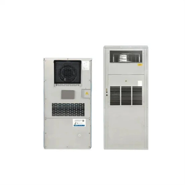
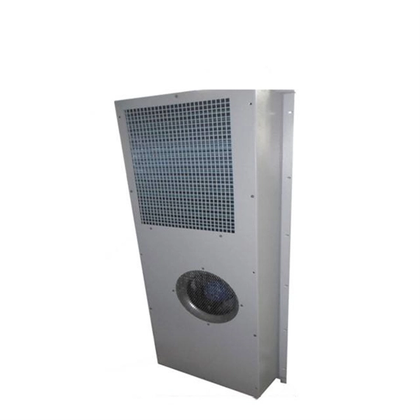
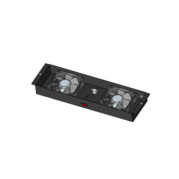
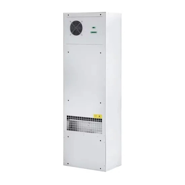
Outdoor Climate Cabinets
IP55/IP66 outdoor enclosures with integrated cooling/heating, -40°C to +55°C operation.
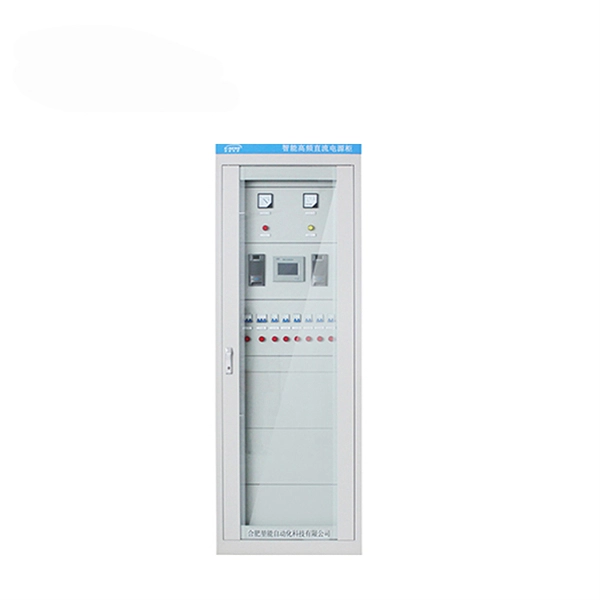
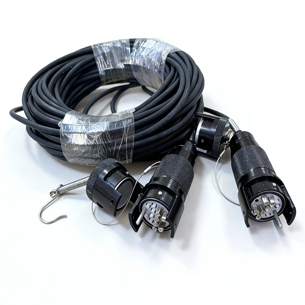
Smart PDUs & Power Distribution
Intelligent PDUs with remote monitoring, per-outlet switching, and environmental sensors.
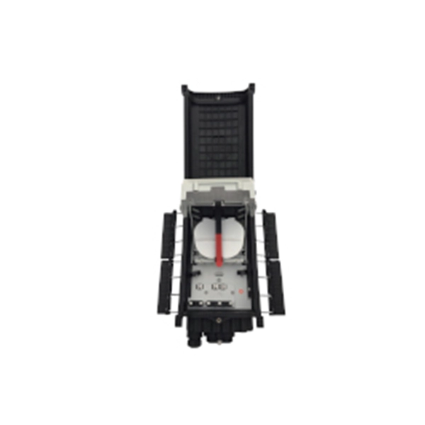
Shelters & Network Cabinets
Prefabricated telecom shelters, emergency comms shelters, and network cabinets with cable management.