
Block diagram of base transceiver station (BTS) site and complete power
The TE includes Block diagram of base transceiver station (BTS) site and complete power system the power amplifiers (PA), transceivers (TRX), digital signal processing (DSP), and...
Communication System Block Diagram, Elements,Types, Examples
The above block diagram of a communication system illustrates the flow of information, signals, and data between different components. It helps in understanding the system architecture,

Communications System Power Supply Designs
Unique solutions for DSL, VoIP and 3G Base Stations illustrate the wide range of power system architectures and the opportunities available for higher level integration.

Block Diagram of Communication System with Detailed Explanation
The essential components of a communication system are information source, input transducer, transmitter, communication channel, receiver and destination. Now, we shall discuss the

AN55427 Infineon Powerline Communication Board Design Analysis
A block diagram of the PLC solution with the CY8CPLC20 programmable PLC chip is shown in Figure 1. To interface the device to the powerline, a coupling circuit is required.
Schematics and docs needed for communication systems of
IEEE Std C37.1 discusses the importance of block diagrams, addressing the communication block diagram in more detail. The communication block diagram provides a similar function for the
Communication station power distribution system diagram
Communication power supply specifically refers to the power supply directly provided to communication equipment. Communication power supply is the main and key part of communication station power
Power Supply in Telecommunications
13.1.5 Survey Diagram, Block Diagram and Functioning Principle of the d.c./a.c. Inverter. Module 2.5 kVA 266.
Block diagram of base transceiver station (BTS) site and
The TE includes Block diagram of base transceiver station (BTS) site and complete power system the power amplifiers (PA), transceivers (TRX), digital signal

Communication System Block Diagram,
The above block diagram of a communication system illustrates the flow of information, signals, and data between different components. It helps in
Building a Better –48 VDC Power Supply for 5G and
Figure 1 presents a simplified diagram of a typical telecommunications DC power system with an emphasis on how –48 V DC is created and distributed.

Base Station Power Supply
Find the perfect block diagram with our step-by-step guide below. Start by choosing a solution, then refine your selection as the next fields adapt dynamically to lead you to the final diagram. Base
Telecom Racks & Cabinets
19-inch racks, wall-mount cabinets, open frames with high load capacity and seismic rating.
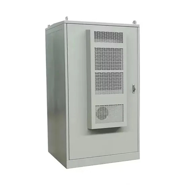
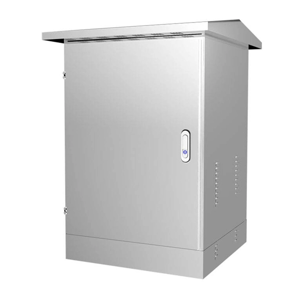
Outdoor Climate Cabinets
IP55/IP66 outdoor enclosures with integrated cooling/heating, -40°C to +55°C operation.
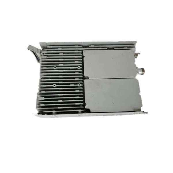
Smart PDUs & Power Distribution
Intelligent PDUs with remote monitoring, per-outlet switching, and environmental sensors.
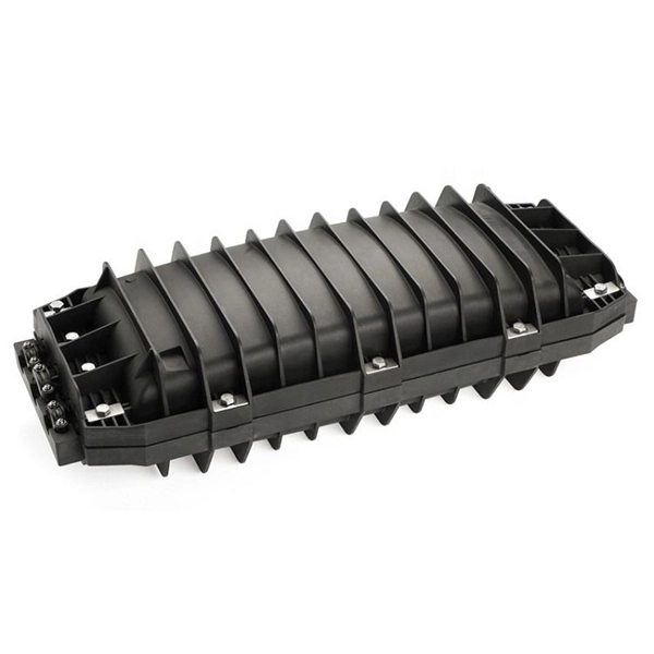
Shelters & Network Cabinets
Prefabricated telecom shelters, emergency comms shelters, and network cabinets with cable management.