Understanding The Anatomy of a Telecommunication Tower
The design and placement of antennas, transmitters, and receivers on the tower are meticulously planned to ensure optimal signal transmission and reception. Understanding the
Telecommunication Tower Reinforced Concrete Foundation
Telecom (Telecommunications) towers are a generic description of radio masts and towers built primarily to hold telecommunications antennas. As such antennas often have a large area and must
ANALYSIS AND DESIGN OF COMMUNICATION TOWER
The maximum story displacement at seismic X direction for a communication tower will depend on several factors, such as the seismic hazard of the location, the structural design and detailing, and
(PDF) Design of telecommunication tower
Telecommunication towers are essential infrastructure in modern communication networks, requiring robust designs to withstand environmental factors such as wind, seismic forces, and temperature
Telecom Tower Design Specifications | PDF | Equipment | Mechanical
The document contains a technical diagram showing the layout and dimensions of components on a telecommunications tower, including antennas, dishes, copper piping, and doors.
How Telecommunication Towers Work: The Backbone of Wireless
Telecom towers transmit and receive RF signals, forming a network of cells that enable communication. They are built as monopoles, lattices, or guyed structures, each tailored for location
analysis and design of telecommunication tower | PPTX
This document details the analysis and design of a 30-meter high communication tower, focusing on its structural integrity and foundation requirements under various loading conditions, particularly wind load.
COMMUNICATIONS DISTRIBUTION SYSTEM DRAWINGS
PROVIDE SERVICE LOOP FOR ALL HORIZONTAL VOICE, DATA, AND VIDEO CABLES NOT TO EXCEED 10 FEET. LOCATION TO BE DETERMINED BY THE RUPM. PROVIDE (3) 30A SPARE
TSTOWER FOR THE STRUCTURAL ANALYSIS OF
TSTower calculations printout is as detailed as the engineer''s requirements. The printout may include all load calculations, applied forces, resulting deformations,
Telecom Tower Design Specifications | PDF
The document contains a technical diagram showing the layout and dimensions of components on a telecommunications tower, including antennas, dishes, copper
TSTOWER FOR THE STRUCTURAL ANALYSIS OF COMMUNICATION GUYED MASTS
TSTower calculations printout is as detailed as the engineer''s requirements. The printout may include all load calculations, applied forces, resulting deformations, stresses and member assessment.
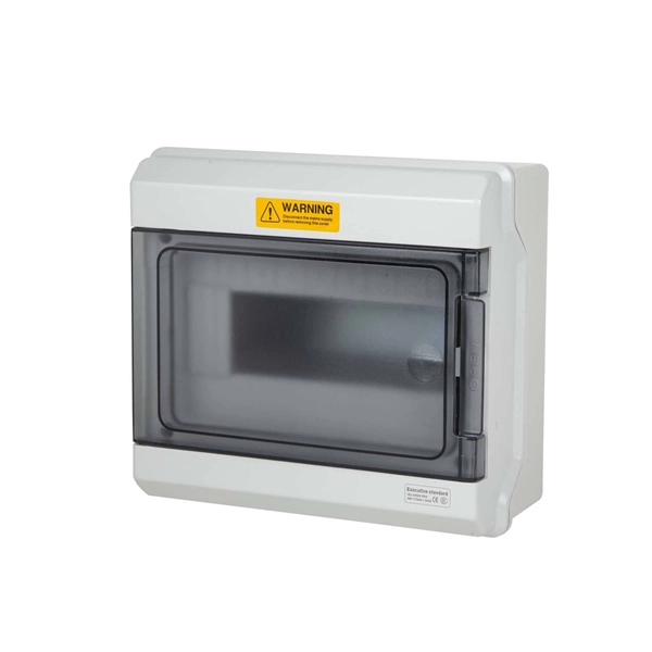
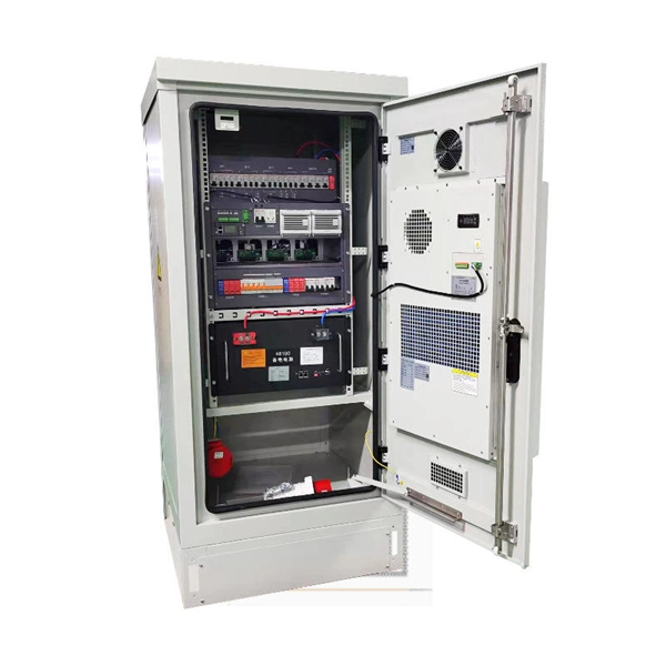
Telecom Racks & Cabinets
19-inch racks, wall-mount cabinets, open frames with high load capacity and seismic rating.
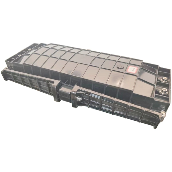
Outdoor Climate Cabinets
IP55/IP66 outdoor enclosures with integrated cooling/heating, -40°C to +55°C operation.
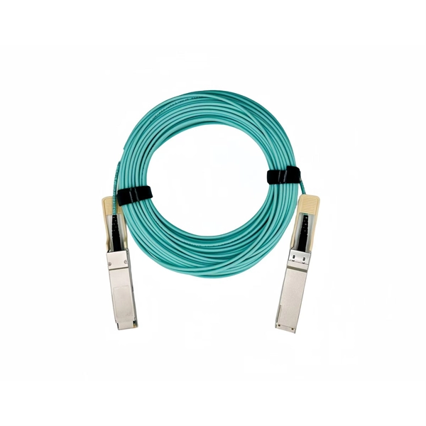
Smart PDUs & Power Distribution
Intelligent PDUs with remote monitoring, per-outlet switching, and environmental sensors.
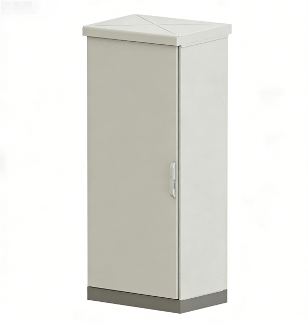
Shelters & Network Cabinets
Prefabricated telecom shelters, emergency comms shelters, and network cabinets with cable management.