-
Optical power meter red light supports remote operation
The Red Light OLP integrates the capabilities of both an OTDR and an OPM in a single device, making it a versatile and convenient solution for network technicians. It utilizes red light technology, which allows for accurate power measurement and characterization of fiber. PG-OPM202 series power meter PG-OPM2020 Hand-held optical power meter, red-light integrated machine series products are mainly used for continuous optical signal power measurement, optical fiber link loss testing and optical fiber line on-off testing. Controlled with a single microprocessor, it is fully functional. Designed for fiber professionals, it covers 7 calibrated wavelengths and is compatible with SC, FC, and ST connectors. GOOD PERFORMANCE: The power meter supports fast and accurate measurement without waiting for warm up, with relative power calculation and self. STD800 series mini Optical Power Meter and red light all-in-one machine series are controlled by single-chip microprocessor but multifunction. The whole machine has automatic shutdown function, three red light modes, backlight display.
[PDF Version]
-
What does light mean in an optical power meter
Simply put, optical power is the "brightness" or "intensity" of light. In optical fiber networks, the units of optical power are often expressed in milliwatts (mw) and decibel milliwatts (dbm). The relationship is: 1mw=0dbm, that is to say, 2mw=3dbm, 10*lgmw is the dbm value. The term usually refers to a device used for measuring the average power in fiber optic systems. In fiber optics, when a beam of light which carries a signal goes through the. This instrument is a high precision, compact, hand held light measurement instrument designed to be at home in the lab and in the field. The power. Definition: delivery of power for electronic devices via light in an optical fiber which is converted to electricity Alternative terms: power-over-fiber, photonic power Category: fiber optics and waveguides Related: fibers fiber cables laser diodes fiber optics Page views in 12 months: 3730 DOI:.
[PDF Version]
-
Quotation for Low-Loss Optical Power Meter Light Source Project
Tier-1 certification kit with power meter and light source, compatible with multiple duplex and multi-fiber connectors up to 24 fibers. Measures loss, length, and polarity in just 1 second, as per certification standards. When placing tones on the fiber using a Tempo. Reduce test time and errors: Wave ID (Dual or Single) decreases test time while reducing technician errors and CW mode provides continuous output (no encoding). Supported output modes: Test Tone (2000, 1000, 330, 270 Hz) for use in fiber identification with AFL brand power meters, OTDRs (with fiber. GouMax Tunable Lasers deliver high-performance CW operation with fast tuning, stable high power output, and seamless wavelength coverage (1250-1650 nm). Supporting single-band (O/E/S/C/L/U), combined-band (O+E, C+L, etc. This versatile tool is useful for measuring both continuous and pulsed laser power, meeting the needs of research and development as well. Native duplex and multifiber (up to 24 fibers). Optical power meters measure the average optical power (energy per unit time) of continuous-wave (CW) or high-repetition-rate pulsed light sources.
[PDF Version]
-
How to test the optical power of a light source using a power meter
To use a power meter for fiber optic testing, always clean connectors first with lint-free wipes or click-to-clean tools. Select the correct wavelength and set your reference. You measure optical power in dBm or insertion loss in dB. Consistent procedures ensure accuracy. Just go to the topics below to find the information you. Fiber optic loss testing is an essential part of maintaining reliable, high-performance fiber optic networks because it helps identify potential issues and ensures that the system meets the required performance specifications.
[PDF Version]
-
Automatic Calibration Procedure for Optical Power Meter
This application note demystifies how EXFO's IQS-12002 Optical Calibration System can guide you through the calibration of power meters, covering issues such as traceability and technical characteristics of detectors, while explaining the procedure in detail. This paper describes the measurement standards, techniques, systems, and. Optical power meters are designed to measure optical power in a specified wavelength range as accurately as possible. Due to the fact that this capability largely depends on the quality of the calibration process, it is important to carefully select your calibration provider. NIST developed a testing system to provide absolute power calibrations for optical power meters. Remember that an accurate power reading depends on regular calibration. Finding ways to optimize the performance of test equipment is one of the primary issues for managers, yet maintaining a large inventory of test and measurement equipment requires a systematic and efficient approach.
[PDF Version]
-
Algeria High-Precision Optical Power Meter Smart Labeling
This document provides a free, but shortened demonstation of our compliance label information for Algeria. Embassies worldwide by Commerce Department, State Department and other U. agencies' professionals Labeling and Marking Requirements Algerian government regulations stipulate that. FHP2 Series Optical Power Meter is the advanced version of OPM series. FHP2 series optical power meter together with FHS2 series laser source, can be used to. Gentec-EO offers a wide range of high accuracy laser power meters suitable for all professional uses that require a precision measurement, from industrial to medical and even scientific uses. Depending on your laser specifications and needs, you can purchase a laser power measurement system by. An essential device in today's field toolkit which combines seamless reporting capabilities and ease of use in a pocket-sized form factor. Evolutive by nature, the solution upgrades over time to help you meet new challenges. Power metering plays a crucial role in accurately measuring and monitoring electricity consumption.
[PDF Version]
-
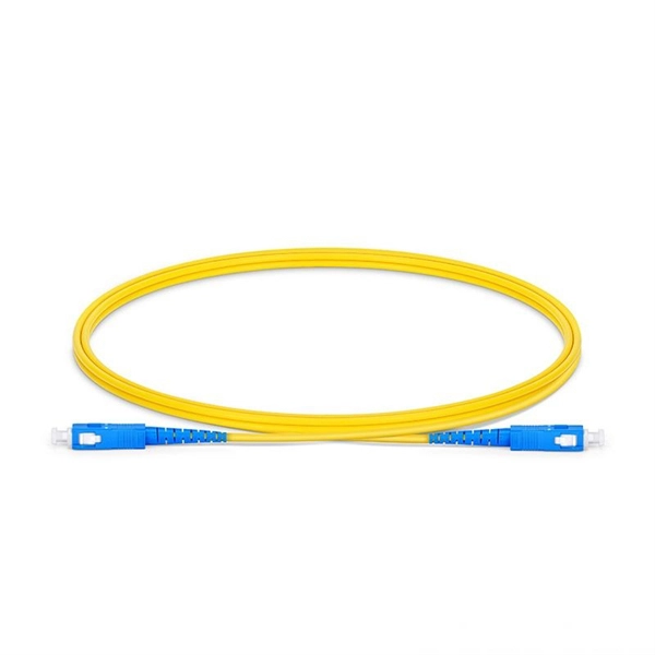
Is it normal to test fiber optic patch cords with a red light pen
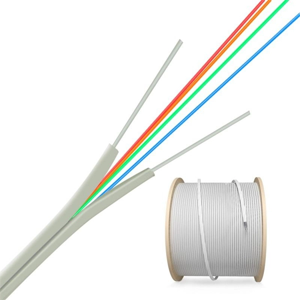
Turn on the red light pen's constant light mode (slide the switch upward) and inspect the optical fiber for red light. A clear red light indicates acceptable continuity. When inspecting bare fibers, fiber spool, and checking splice points of fiber optic patch cord cable, Yingda recommends using a red light pen (also called visual fault locator, VFL) to perform connectivity tests and quickly locate fault points. This method is widely used in telecommunications and. Visual Fault Locator (VFL) testing is one of the most fundamental inspection methods used in FTTH, ODN, and data center environments. A VFL emits a visible red laser (typically 650 nm) that travels along the fiber core and leaks out at points of excessive loss, fiber breaks, or microbends. The VFL helps you do these tasks: Quickly verify the.
[PDF Version]
-
Optical power meter received power
An optical power meter (OPM) is a device used to measure the power in an optical signal. The term usually refers to a device for testing average power in fiber optic systems. Other general purpose light power measuring devices are usually called radiometers, photometers, laser power meters (can be photodiode sensors or thermopile laser sensors), light meters or lux meters. A typical optic. SensorsThe major types are (Si), (Ge) and (InGaAs). Additionally, these may be used with attenuating elements for high optical power testing, or wavelengt. A typical OPM is linear from about 0 dBm (1 milli Watt) to about -50 dBm (10 nano Watt), although the display range may be larger. Above 0 dBm is considered "high power", and specially adapted units may measure u. Optical Power Meter and accuracy is a contentious issue. The accuracy of most primary reference standards (e.g.,, Length,, etc.) is known to a high accuracy, typically of the orde.
[PDF Version]
-
Instruction on Measuring Optical Decoration with an Optical Power Meter
This is your "QuickStart" guide to testing optical power in fiber optic communications systems with a fiber optic power meter. We'll give you the basic information you need and provide some printable references. Just go to the topics below to find the information. Page 1 Operation Manual Thorlabs Instrumentation Optical Power Meter System PM120, PM121, PM122, PM130, PM132, PM140, PM144 PM210, PM212, PM213 2006. 2006 © Copyright 2006, Thorlabs. Always clean connectors before testing. This prevents dust from affecting your measurements. Select. BN 2302/03/13 measure power levels on fiber optical systems. Battery operation from two AA batteries and the robust, shock-proof design provide long. This guide provides instructions for an experienced technician to begin using the Extron Fiber Optic Power Meter (FPM 101) and Light Source (FLS 101). The Extron Fiber Optic Test Set includes all the tools needed to measure optical power and cable loss in multimode (MM) and singlemode (SM) fiber.
[PDF Version]
-
How to solve the problem of an inaccurate optical power meter
When working with automated power meters, you'll need to verify both linearity factor and input optical conditions that can introduce power accuracy issues. Your calibration process should address average power measurements with documented measurement uncertainty values. A send"'optical power meter is correctly calibrated when using a equivalent testing practices. Below are general answers on how to operate, maintain, and calibrate an optical fiber ranger from the list of GAO Tek's optical power meters. Power On: Ensure the device is charged or properly connected to a power source. Ephraim Greenfield The total accuracy of measurement of a laser power/energy meter is affected by the following factors: The calibration¹ uncertainty of the measuring sensor. Fluctuating optical power often results in: Common root causes include connector contamination, bending loss, or poor mechanical contact. Low power or unstable OSNR forces Forward Error Correction to work harder.
[PDF Version]
-
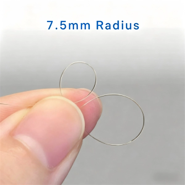
Fiber optic red light pen red light source breakpoint fault
This pen shaped visual fault locator is a tool used on terminated fiber optic cables to locate sharp bends or breaks in jacketed or bare fiber. Its red laser shines through most yellow-jacketed optical fibers to help you pinpoint breaks, bends, faulty connectors, splices and other causes of signal loss. It has a reach of up to. Fiber Optic Red Light Pen Tester VFL (Visual Fault Locator) - 1mW - 2. Let's dive into everything you need to know about mastering VFLs. 650nm Pen-type Visual Fault Finder for fiber tracing, fiber routing and continuity checkingIt features a red design, a universal connector and an accurate measurement.
[PDF Version]
-
Is a negative reading on the optical power meter normal
This negative reading is normal and indicates the expected passive loss of light over distance and through network components. After all, lasers produce positive optical power, so how could a sensor display, for example, −5 W? With thermopile-based laser power sensors, the answer usually lies in the temperature gradient inside the. Zero dBm is defined as exactly one milliwatt. The power received at the Optical Network Terminal (ONT) is virtually always less than one milliwatt, resulting in the received signal strength being expressed as a negative number, such as -20 dBm. The “m” in dBm refers to the reference power which is 1 milliwatt. 1 milliwatt and +10 dBm is 10 milliwatts. Fiber optic sources. Why incorrect power readings occur Incorrect readings most commonly arise from: How this affects network judgment Misinterpreted power levels often lead to: Why it is widely misunderstood Many technicians treat power meters as “pass/fail devices. And where either too high or too low a number can signal a malfunction in the device. Besides, understandingthe readings most definitely helps us establish.
[PDF Version]
-
Optical Power Meter Efficiency Calibration
Optical power meter calibration is a critical process that ensures the accuracy and reliability of power measurements in fiber optic systems. This sophisticated procedure involves comparing the readings of a device under test with a reference standard to establish and maintain. Finding ways to optimize the performance of test equipment is one of the primary issues for managers, yet maintaining a large inventory of test and measurement equipment requires a systematic and efficient approach. References coUimated beam or optical fiber/connector configurations. Due to the fact that this capability largely depends on the quality of the calibration process, it is important to carefully select your calibration provider. NIST developed a testing system to provide absolute power calibrations for optical power meters.
[PDF Version]
-
How to connect an optical power meter to an optical fiber
Disconnect the reference cable from the meter and connect it to the fiber link under test. This value shows the total insertion loss. Tip: The one-jumper method includes losses at both ends, simulating. An optical power meter measures the strength of light traveling through a fiber optic cable, giving you a reading in dBm (decibels relative to one milliwatt). All are written in the same straightforward format: what equipment do you need, what are the procedures for testing, options in implementing the test, measurement errors and documenting the results. Consistent procedures ensure accuracy. Verify light travels from. Below are general answers on how to operate, maintain, and calibrate an optical fiber ranger from the list of GAO Tek's optical power meters.
[PDF Version]
-
How to interpret a laboratory optical power meter
To use a power meter for fiber optic testing, always clean connectors first with lint-free wipes or click-to-clean tools. Select the correct wavelength and set your reference. You measure optical power in dBm or insertion loss in dB. It's very useful in many jobs, especially in communications, fiber optics, andelectronics. All of our surgical devices and whether they are working correctly and producing the appropriate amount. An optical power meter (OPM) is a device used to measure the power in an optical signal. Typically both transmitters and receivers have receptacles for fiber optic connectors, so measuring the. We describe the results of a comparison of reference standards between the National Institute of Standards and Technology (NIST, USA) and Laboratorio de Metrología, Instituto Costarricense de Electricidad (LAMETRO-ICE, Costa Rica) for optical fiber–based power measurements at wavelengths of 1310.
[PDF Version]
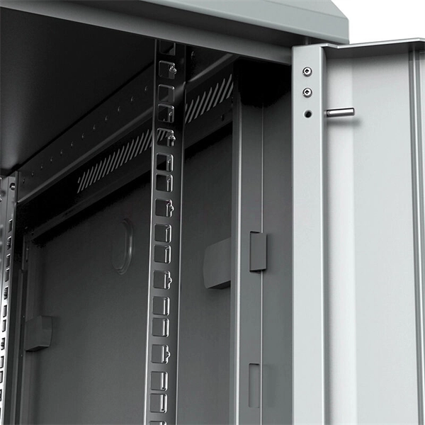
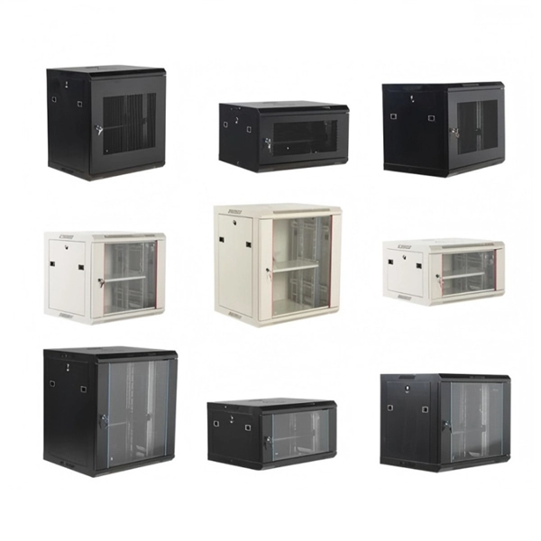
Telecom Racks & Cabinets
19-inch racks, wall-mount cabinets, open frames with high load capacity and seismic rating.
Outdoor Climate Cabinets
IP55/IP66 outdoor enclosures with integrated cooling/heating, -40°C to +55°C operation.
Smart PDUs & Power Distribution
Intelligent PDUs with remote monitoring, per-outlet switching, and environmental sensors.
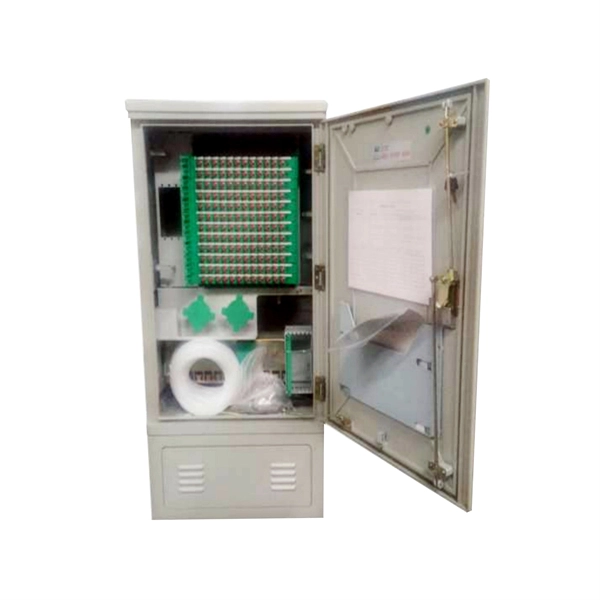
Shelters & Network Cabinets
Prefabricated telecom shelters, emergency comms shelters, and network cabinets with cable management.